
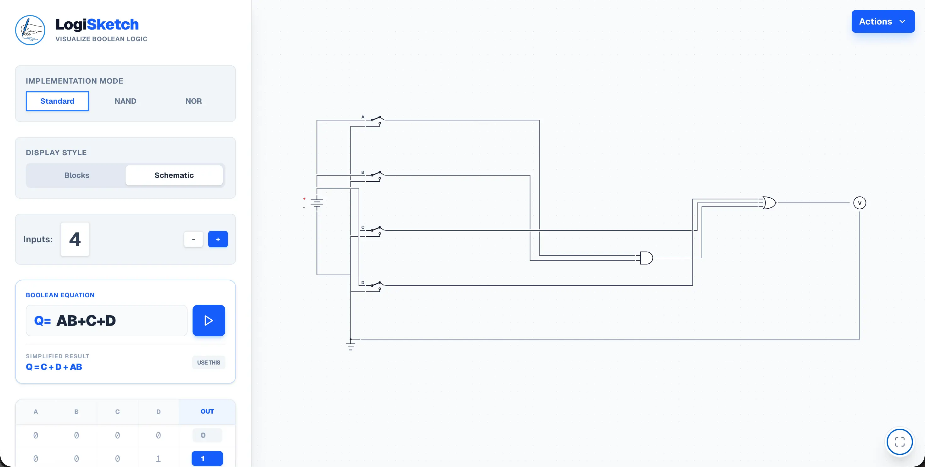
LogiSketch
Type a Boolean expression; get a minimized, routed NAND/NOR circuit.
- Role
- Sole developer
- Timeline
- Five weeks, Feb 11 to Mar 18, 2026
- Team
- Solo
- Stack
- Next.js
- TypeScript
- Tailwind
- Result
- Classmates use it in PHYS 160 and CSCI 50.02
Ten minutes per equation
In digital logic class, we're often handed a scary-looking equation and asked to simplify it. Something like this:
F = A'B'CD' + A'B'CD + A'BC'D + A'BCD' + A'BCD + ABC'D + ABCD
That's ten minutes to prove it's fully simplified, then more time to draw the circuit by hand. After dozens of repeats, I kept thinking: is there a way to speed this up? And while I was at it, what if the tool could also take a change in the truth table, so experimenting got easier?
So I built it. Ta-da: LogiSketch.
Algebra, but cheaper
Boolean equations work like algebra. You can write the same thing a dozen ways until you factor it down. The difference is that here, simplifying saves money: fewer terms means fewer gates, and fewer gates means less hardware.
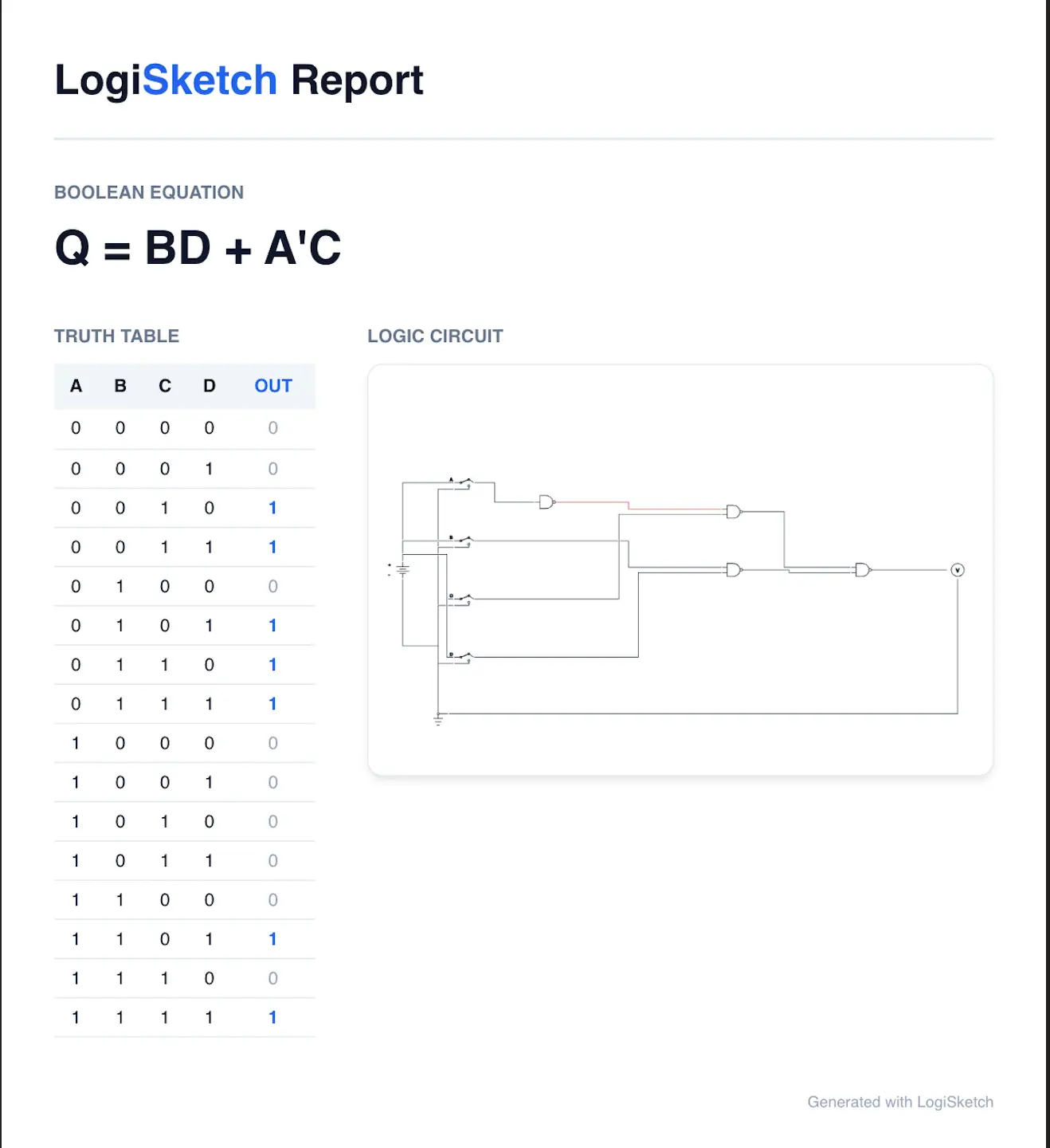
Type an equation, and LogiSketch parses it, builds the full truth table, and minimizes it with the Quine–McCluskey algorithm. That algorithm keeps merging terms that differ by a single bit (110 and 111 become 11-, because the last bit stopped mattering) until nothing else merges. That equation above? BD + A'C.
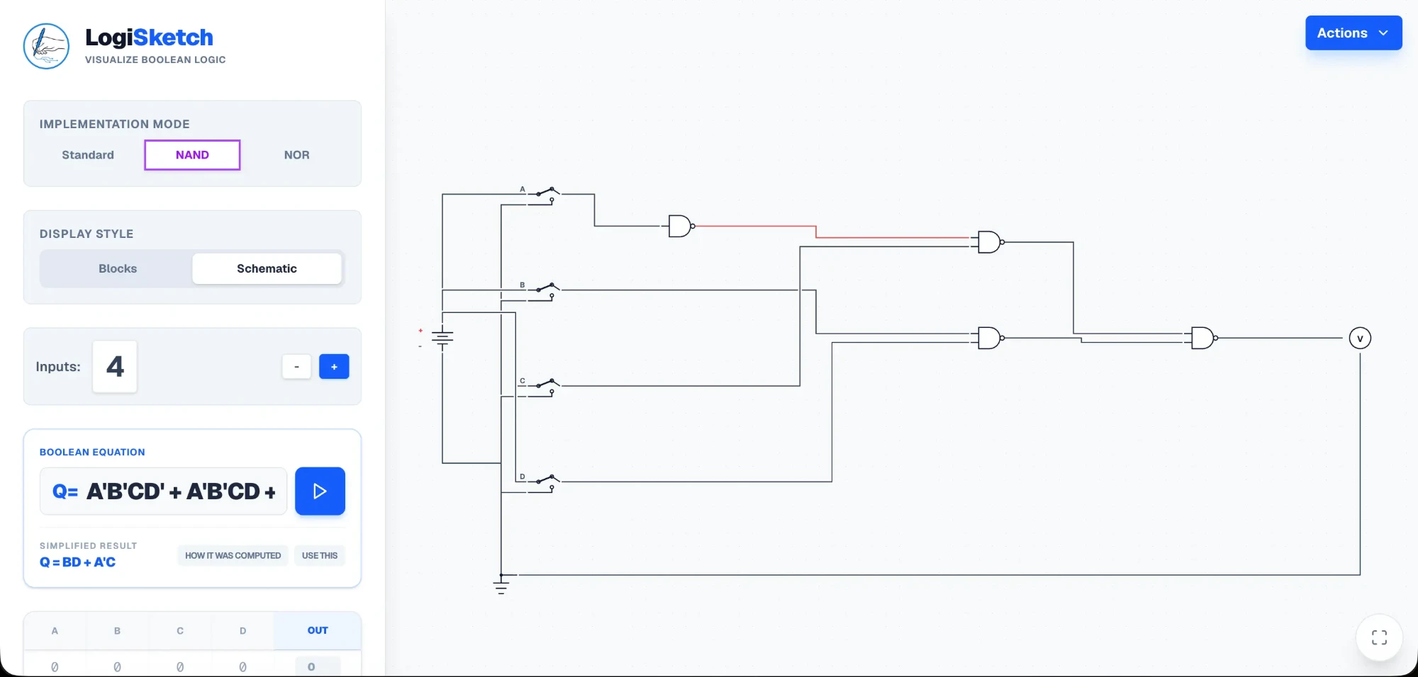
Then it draws the circuit in standard gates, NAND only, or NOR only. For NAND, De Morgan's laws turn the usual AND-OR circuit into NAND-NAND without changing what it does. It works the other way too: edit the truth table, and the minimal equation updates itself.
Making a circuit look like a circuit
The logic was the easy part. The hard part was making the circuit look like one. My first version got the logic right, but the wiring was a tangled mess nobody would ever draw on paper.
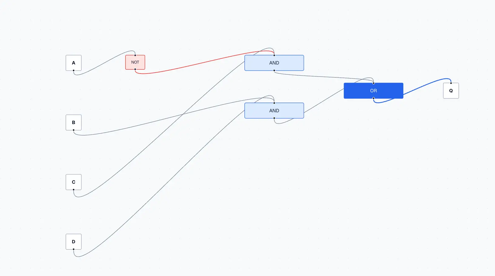
The real problem was crossings. The computer couldn't tell when two wires should connect and when they should just pass each other. The fix: when a vertical wire crosses a horizontal one without connecting, it leaves a gap and sits on top. Then I wrote a router that gives power and ground their own vertical lanes, the way engineers draw them, and keeps every wire to straight lines and sharp corners. That's when it finally read like a schematic. (The fix logs are in the GitHub repo, for the curious.)
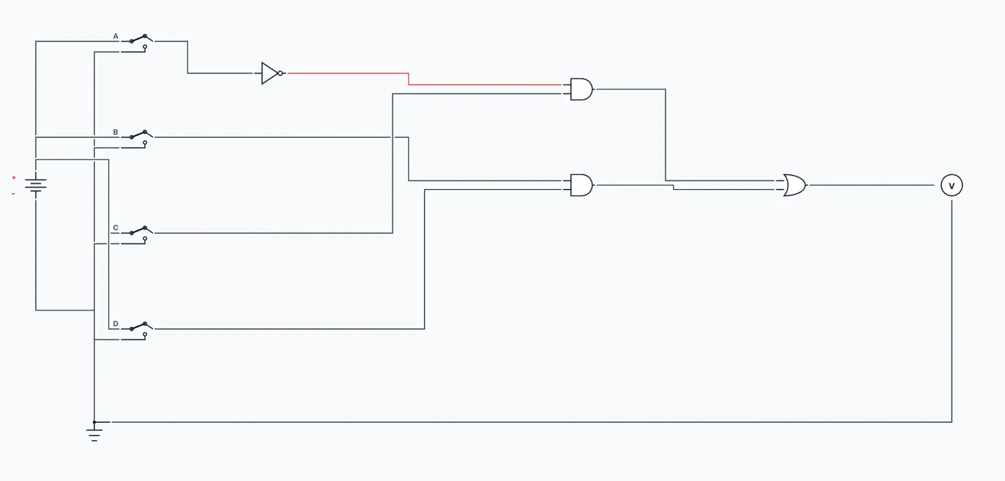
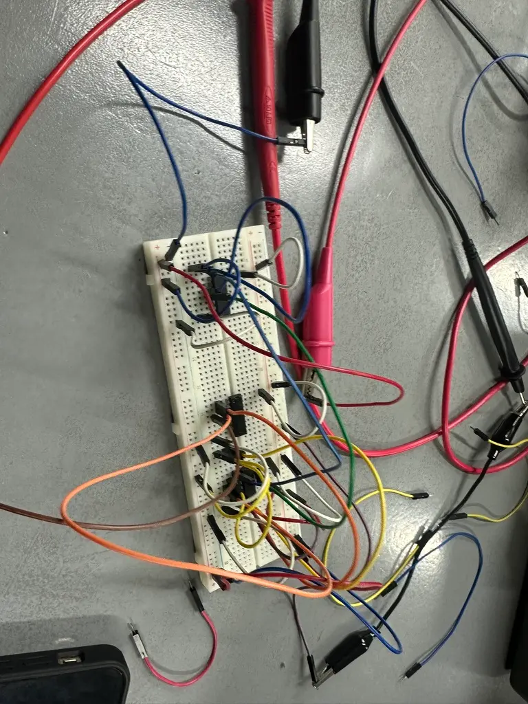
That matters off the screen, too, because the schematic is a wiring guide. In lab, circuits like this one end up on a breadboard.
What I'd do next
Nothing urgent. If it picks up enough traction, I'd add K-maps, plus a setting that lets you mix NAND, NOR, and XOR gates in one circuit.
Why it made the four
This was my turning point: my first real project built to solve a problem for me and the people around me. I built it for myself first. Then classmates saw me using it, and started using it too.
I thought it would be a one-course wonder, just for PHYS 160 (Electronics). Then we started simplifying things in CSCI 50.02 (Computer Organization Lab), and out it came again. I still use it today, for quick simplification and as a wiring guide.
Not bad for a one-course wonder.